
|
Be the first user to complete this post
|
Add to List |
335. Max Flow Problem – Introduction
Max Flow Problem-
- Maximum flow problems find a feasible flow through a single-source, single-sink flow network that is maximum.
- This problem is useful for solving complex network flow problems such as the circulation problem.
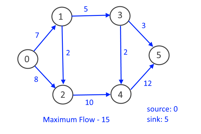
- The maximum value of the flow (say the source is s and sink is t) is equal to the minimum capacity of an s-t cut in the network (stated in max-flow min-cut theorem).
- In maximum flow graph, Incoming flow on the vertex is equal to outgoing flow on that vertex (except for source and sink vertex)
Example:
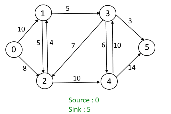
Given the graph, each edge has a capacity (the maximum unit can be transferred between two vertices). Find out the maximum flow which can be transferred from source vertex (S) to sink vertex (T).
Greedy Approach:
This approach may not produce the correct result but we will modify the approach later.
- Max_flow = 0
- Use BFS or DFS to find the paths.
- While(Path exist from source(s) to destination(t) with capacity > 0)
- Find the minimum_flow (minimum capacity among all edges in path).
- Add minimum_flow to the Max_Flow.
- Reduce the capacity of each edge by minimum_flow.
- Return Max_flow.
Let’s understand it better by an example
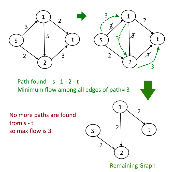
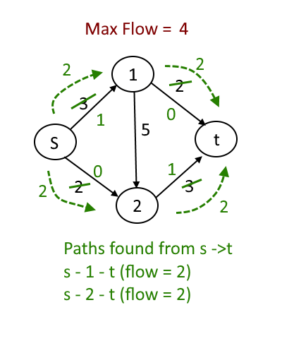
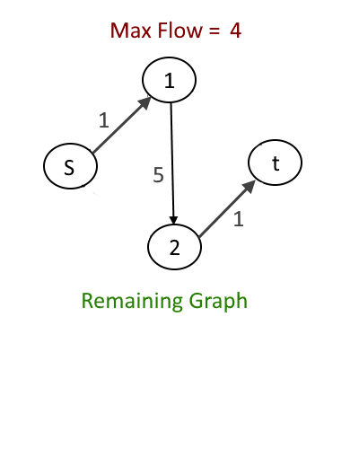
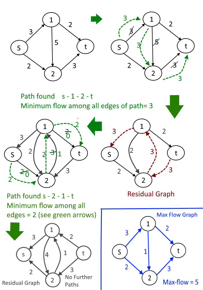
- Choose path S-1-2-t first
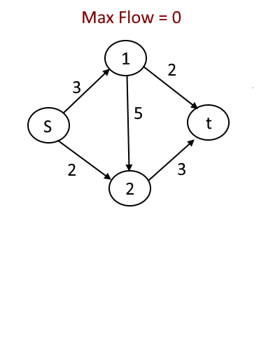
Now let’s take the same graph but the order in which we will add flow will be different. See the animation below.
- Choose path S-1-2-t later
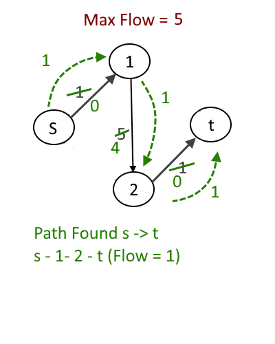
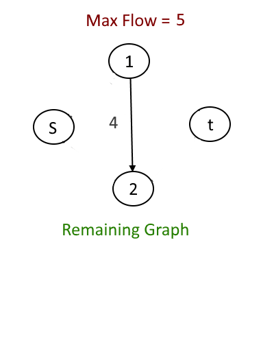
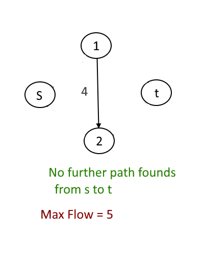
Now as you can clearly see just by changing the order the max flow result will change. The correct max flow is 5 but if we process the path s-1-2-t before then max flow is 3 which is wrong but greedy might pick s-1-2-t . That is why greedy approach will not produce the correct result every time.
We will use Residual Graph to make the above algorithm work even if we choose path s-1-2-t.
Residual Graph:
The second idea is to extend the naive greedy algorithm by allowing “undo” operations. For example, from the point where this algorithm gets stuck (Choose path s-1-2-t first, our first approach), we’d like to route two more units of flow along the edge (s, 2), then backward along the edge (1, 2), undoing 2 of the 3 units we routed the previous iteration, and finally along the edge (1, t). This would yield the maximum flow, same as (Choose path s-1-2-t later, our second approach)
See the approach below with a residual graph.
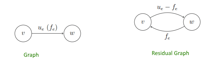
We need a way of formally specifying the allowable “undo” operations. This motivates the following simple but important definition, of a residual network. The idea is that, given a graph G and a flow f in it, we form a new flow network Gf that has the same vertex set of G and that has two edges for each edge of G. An edge e = (v, w) of G that carries flow fe and has capacity ue (Image below) spawns a “forward edge” (u, v) of Gf with capacity ue −fe (the room remaining)and a “backward edge” (w, v) of Gf with capacity fe (the amount of previously routed flow that can be undone)
Further, we will implement the Max flow Algorithm using Ford-Fulkerson
Reference: Stanford Edu and GeeksForGeeks